Have a Question?
-
Injection Sprayers
-
-
-
- ASM-3320-V2 – Skid Honda Engine / Water Pump Assembly
- Water Pump Inlet Plumbing V3 – Skid – Gas
- Water Pump Inlet Plumbing V3 – Skid – Hydraulic
- Water Pump Outlet Plumbing V3 - Skid - Gas
- Water Pump Outlet Plumbing V3 - Skid - Hydraulic
- Water Pump Outlet Plumbing V4 - Skid - Gas
- Water Pump Outlet Plumbing V4 - Skid - Hydraulic
-
-
- RS6000 Gas Injection Skid Sprayer Manual V5.0
- RS6000 Gas Injection Skid Sprayer Manual V6.0
- RS6000 Gas Injection Skid Sprayer Manual V6.0 w/ Cannon Plug
- RS6000 Gas Injection Skid Sprayer Manual V6.1
- RS6000 Gas Injection Skid Sprayer Manual V6.1 w/ Cannon Plug
- RS6000 Gas Injection Skid Sprayer Manual V6.3 w/ Cannon Plug
- RS6000 Gas Injection Skid Sprayer Manual V6.4
- RS6000 Gas Injection Skid Sprayer Manual V6.4 w/ Cannon Plug
- RS6000 Gas Injection Skid Sprayer Manual V6.5
- RS6000 Gas Injection Skid Sprayer Manual V6.5 w/ Cannon Plug
- RS6000 Gas Injection Skid Sprayer Manual V6.6 w/ Cannon Plug
-
Anti-Icing Sprayers
-
Search Support
Categories
TASC Error 0
Problem
The TASC console displays the message Error 0 when attempting to spray.
Definition of Problem
An Error 0 condition indicates one of the required calibration numbers the TASC uses to calculate pump demand is set at 0.
Solution
Change the TASC mode switch to Setup. Turn the display rotary switch to the following positions and review the calibration numbers displayed. Use the Increase / Decrease switch to adjust the calibration number as required. We have listed the most common calibration numbers below for your reference.
Carrier Applied
The Carrier Applied position holds the flow meter calibration number. It is used to calculate the carrier application total.
Polmac Flow Meters
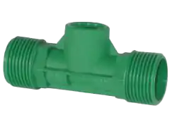
3/4" Flow Meter
Calibration Number: 396.9
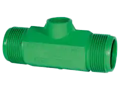
1" Flow Meter
Calibration Number: 153.1
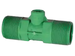
1 1/2" Flow Meter
Calibration Number: 38.8
Teejet Flow Meters
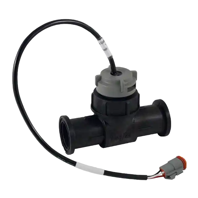
801 Flow Meter
Calibration Number: 310
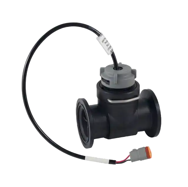
802 Flow Meter
Calibration Number: 79
Width
The width position holds the widths of each boom section. It also holds the Boom C width, which is what the TASC console uses when calibrating the injection pumps.
| Section | Norstar Standard Width |
|---|---|
| Boom C | 120" |
| 1 | 24" |
| 2 | 24" |
| 3 | 48" |
| 4 | 48" |
| 5 | 48" |
| 6 | 72" |
| 7 | 72" |
| 8 (Spray Bar) | 108" |
| 9 (Curb Nozzle) | 24" |
Distance
The distance position holds the calibration number for the ground speed sensor. In most cases, this will be a radar unit mounted on the chassis or skid.
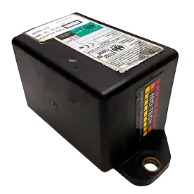
Mid-Tech Compact Radar
Starting Calibration #: 780
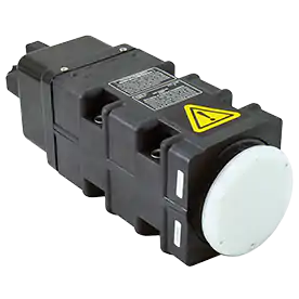
Dickey-John RVS II Radar
Starting Calibration #: 1000
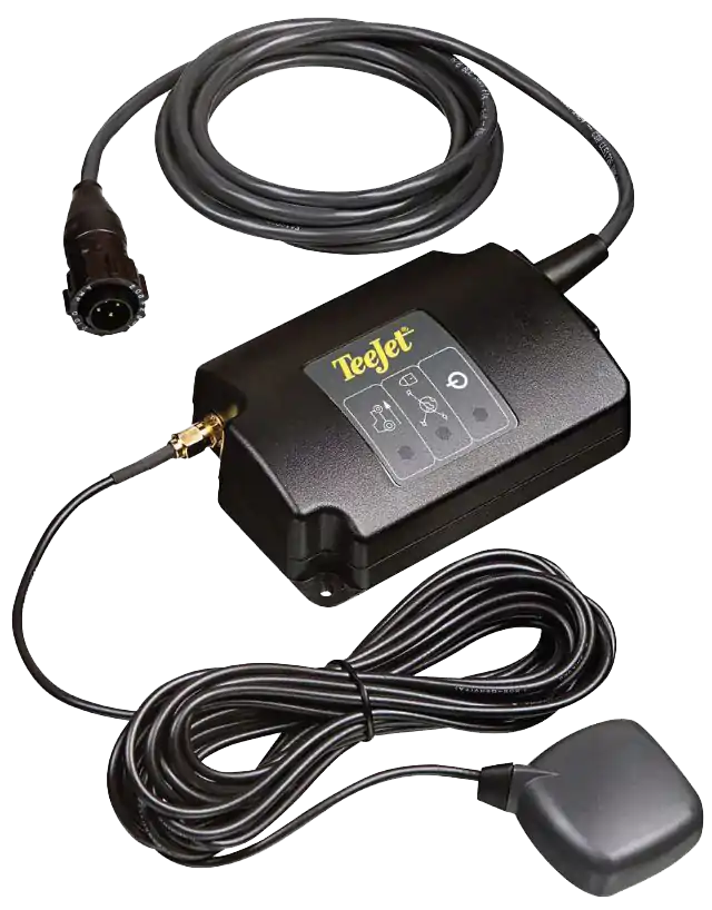
GPS Speed Sensor
Starting Calibration #: 769
Chemical Applied
The chemical applied position holds the calibration numbers for the pump tube(s) installed in the pumps. You can only turn on one pump switch at a time to adjust the calibration numbers.
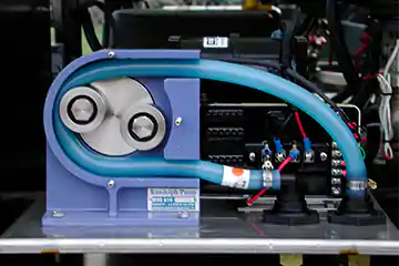
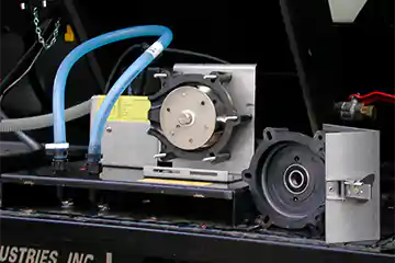

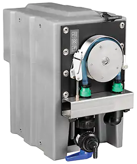
MT500 Injection Pump
| Tube Size (ID) | QD Color | Cal # |
|---|---|---|
| 3/16" | Red | 32 |
| 1/4" | Blue | 55 |
| 3/8" | Green | 110 |
| 1/2" | Yellow | 150 |
Chemical Rate
The chemical rate position holds the programmed rates the injection pumps will attempt to maintain while spraying. Only one pump can be active while adjusting the application rate. Any value greater than 0 is an acceptable application rate. Please refer to the product label for the correct application rate.